Simulation-Driven
Engineering
The core strength of Timetooth is its high quality of engineering modeling and simulations support for product development. The services can be leveraged by clients in product conceptualization, prediction/validation of performance, abuse situation study or field issue resolution.
Timetooth uses a selection of industry standard COTS simulation software, as well as a rich library of proprietary software codes and customized open source solutions.
FE Meshing
How it is used
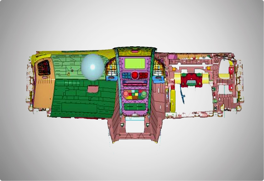
FE meshing is carried out to discretize a geometry containing infinite degrees of freedom to finite degrees of freedom for the subsequent FE Analysis.
Types of FE Meshing
2D meshing (by extraction of the mid surface of the geometry) or by 3D meshing (capturing the overall geometry) are employed for simplification of complex geometry. 0D (lumped mass), 1D (rods, beams, etc), 2D (trias, quads, etc) and 3D (tetra, hex/brick, etc) elements are utilized for meshing depending on the type and complexity of the analysis and geometry.
Static FE Analysis
How it is used
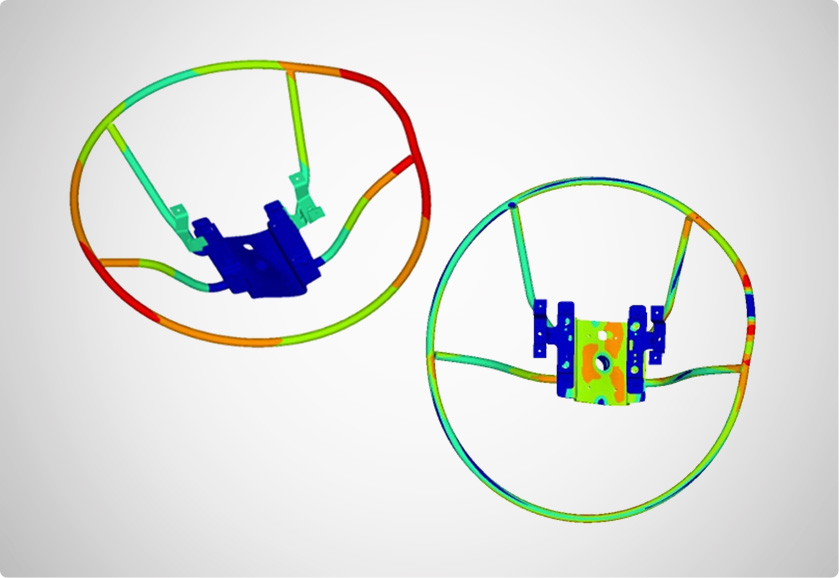
Static FE Analysis is associated with a state of a system that is in equilibrium under an action of balanced forces and torques so that the system remains at rest. Basic equation solved in the FE analysis is given by: Kx = f. Where K= Global stiffness matrix , x = Displacement vector response to be determined. , f = External forces vector applied to the structure. Two different types of Static FE Analyses are carried out: Linear and Non-linear Static FE Analysis.
Linear static FE analysis
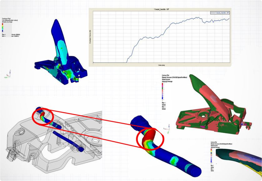
Static structural analysis is the basic approach used to understand the deformation, stress, and strain of an assembly or a component under investigation for a range of loads, ensuring the system’s structural integrity.
Non-linear static FE analysis
Nonlinear analysis should be introduced when the linear solution is not valid anymore. Three main types of Non Linear Static Analysis carried out are:
• Material nonlinearity
• Geometric nonlinearity (Buckling, Creep)
• Boundary and Contact Nonlinearity
Dynamic Analysis
How it is used
Dynamic analysis involves systems where forces vary with parameters such as time/frequency. Types of dynamic analysis involve Free Vibration and Forced Vibration.
Free Vibration
Normal mode Analysis
Modal analysis calculates the frequency modes or natural frequencies of a given system. It verifies if there are rigid modes on the system, and the link between components. Natural frequency of a system is dependent only on the stiffness of the structure, and the mass which participates with the structure (including self-weight) and the boundary conditions, governed by the equation: Mx(..)+Kx = 0 : where K = stiffness matrix of the structure, M = mass matrix.
Forced Vibration
Frequency Response Analysis, Random Response Analysis, Transient Response Analysis
Frequency response analysis is used to calculate the response of a structure under a harmonic excitation. Applications of Forced Vibration are noise, vibration and harshness (NVH) analysis of vehicles, rotating machinery, and transmissions.
Advanced Analysis- Response Spectrum Analysis, Complex Eigenvalue Analysis
Explicit FE Analysis
How it is used
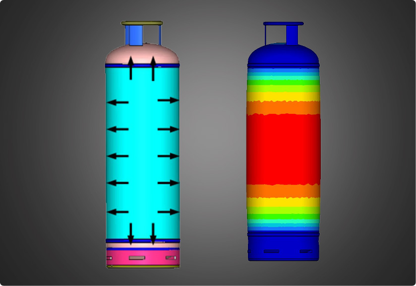
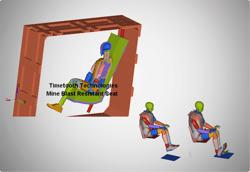
An explicit FE Analysis is used to determine the dynamic response of a structure due to stress wave propagation, impact or rapidly changing time-dependent loads. Explicit type analysis is used where the non-linearity in the solution is so great that standard static analysis is no longer applicable.
Aspects of the analysis
Momentum exchange between moving bodies and inertial effects are usually important aspects of the type of analysis being conducted. In an explicit scheme, velocities and displacements are obtained by direct integration of nodal accelerations.
Where it is used
Some general scenarios where Explicit FE Analysis are used:
· Crash testing/Impact cases
· Metal forming
· Explosive or ballistic events
· ROPS/FOPS Analysis explicit FE analysis is used.
Fatigue Analysis
How it is used
Fatigue failure is the progressive and localized structural damage that occurs when a material is subjected to cyclic loading. Damage models generally used in the fatigue analysis are:
· Stress-Life (S-N) Approach
· Strain-Life (E-N) Approach
Types of fatigue analysis offered
Types of Fatigue Analysis offered are:
· Uniaxial Fatigue Analysis
· Multiaxial Fatigue Analysis
· Spot Weld Fatigue Analysis
· Vibration Endurance Fatigue Analysis
Thermal Analysis
(steady state & transient)
How it is used
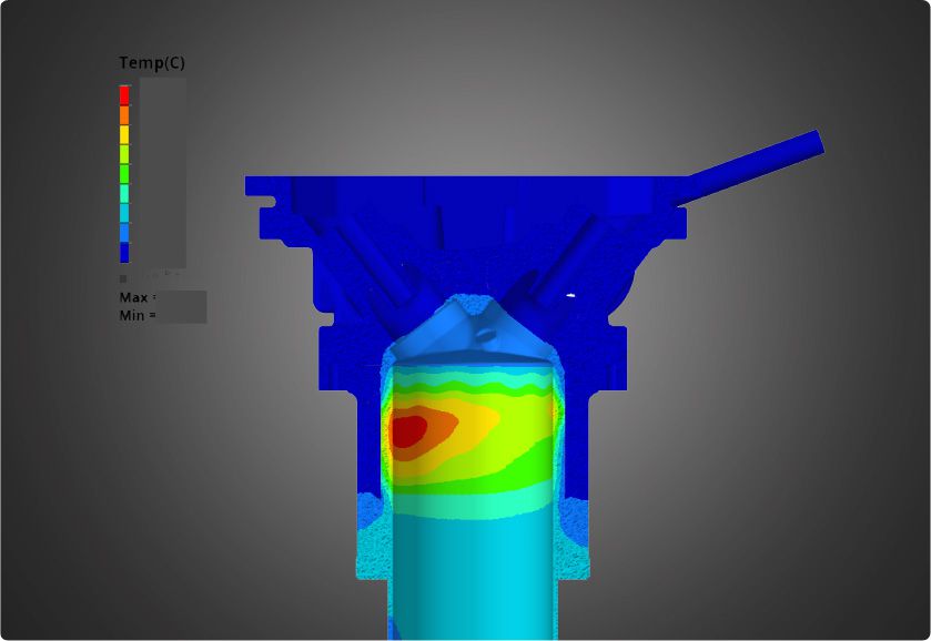
Heat transfer analysis provides solutions for unknown temperatures and fluxes under thermal loading. Temperature represents the amount of thermal energy available, and fluxes represent the flow of thermal energy.
Thermal loading is defined as energy flows into and out of the system. The applied thermal loads can either be time-dependent or time-invariant; transient thermal analysis is used to capture the thermal behavior of a system over a specific period of time.
Transient heat transfer analysis equation
The basic finite element equation for transient heat transfer analysis is given by:
[𝑪]{𝑻̇} + ([𝑲] + [𝑯]){𝑻} = {𝒑}
where C = Heat capacity matrix, K = Conductivity matrix, H = Boundary convection matrix due to free convection, T(.) = Derivative of the nodal temperature matrix with respect to time, Term [C] {𝑇̇} captures the transient nature of the analysis, T= The unknown nodal temperature matrix, f= Thermal loading vector
CFD Analysis
How it is used
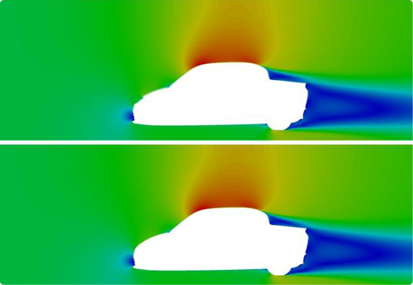
Computational Fluid Dynamics (CFD) is the branch of fluid mechanics where numerical methods are used to analyze fluid dynamics problems.
· Navier-Stokes solver of the CFDs helps solve a full range of flow, heat transfer, turbulence, and non-Newtonian material analysis capabilities.
· Lattice Boltzmann method (LBM) solver enables ultra-fast prediction of the aerodynamic properties of passenger cars, light trucks, race cars, and heavy-duty vehicles.
· Smooth Particle Hydrodynamics (SPH) solver is used to predict fluid flow around complex geometries under complicated motion.

MBD Analysis, Co-Simulation
& Multi-Physics
How it is used
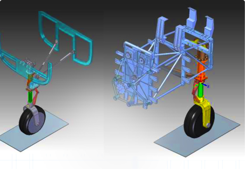
A multibody system is defined as a combination of bodies, components, or sub-structures, connected to each other through joints, force elements, and controls. Bodies can be considered either Rigid or Flexible. Rigid bodies do not undergo deformations. However, neglecting the body deformations can lead to inaccurate results. Thus, some of the bodies are considered flexible, that is they can undergo deformations. Modal reduction procedures are used to include flexible bodies in multibody dynamics simulations.
Types of analysis for multibody systems
Different types of analysis can be performed on a multibody system to determine its behavior under certain loading, applied motion, and initial velocity.
· Transient (kinematic, dynamic) analysis determines the response under time dependent loading.
· Static and quasi-static analyses determine the static equilibrium of a system.
Multiphysics simulation solutions
To simulate a wide range of interacting physical models advanced Multiphysics Simulation Solutions are used.
Integrated solvers platform including structural (OptiStruct and RADIOSS), CFD (AcuSolve), and multi-body dynamics (MotionSolve) analysis are available for Multiphysics Simulation Solutions.
MBS and Co-Simulation Analysis
How it is used
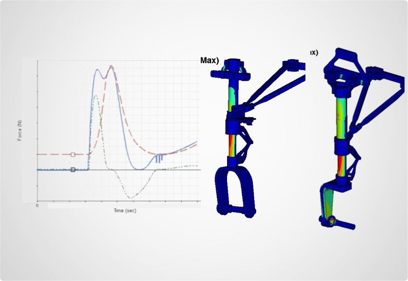
Co-simulation helps to model a dynamic system on a multi-body environment and provides a high-fidelity level system.
Modeling for co-simulation
Special statements and blocks are available for defining the inputs and outputs between an MBS and control-system model.
· Statements to reference inputs and output
· MSPlant (MotionSolve Plant) and MSSignal (MotionSolve Signal) blocks
· MotionView models as input
Optimization
How it is used
A simulation-driven design technique helping reduce the development cycle time of a product by enabling the users identify high-potential solutions.
Benefits of optimization
· Enhanced product designs
· Generation of lightweight manufacturable concepts
· Cost-effective design solutions
Types of optimization solutions
Types of optimization solution provided are:
· Topography Optimization
· Topology Optimization
· Size, Shape, and Free-shape Optimization
· Free Size Optimization